Making Tactile Models with a 3D Printer
The Subaru Telescope: How to Make the Models
Each model consists of a movable section (Fig. 1/Fig. 3) and a base section (Fig. 2/Fig. 4). After assembling the two sections individually, bolt them together using M4-size bolts and nuts. Each stl file is printable without additional support materials. Do not add any support materials. Each stl file should be printable as is after loading into 3D printing software, without needing to adjust the size. But if the pieces look too small or too big, try adjusting the size with the software.
The Detailed Version
- Download package including stl files and manual (zip file, 2.6 MB)
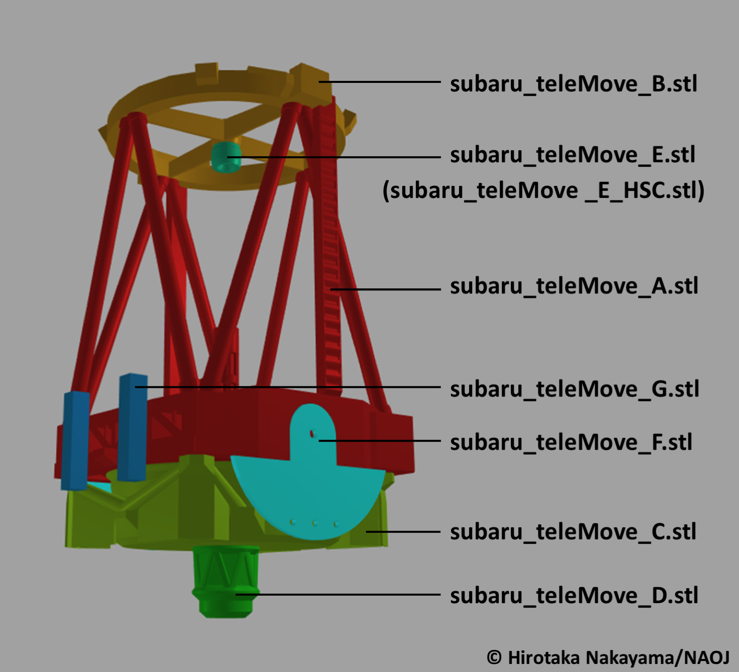
Fig. 1 The movable section
Print one (1) copy of the five (5) parts "teleMove_A" to "teleMove_E" and two (2) copies each of "teleMove_F" and "teleMove_G". The part "teleMove_E_HSC" is optional; it is interchangeable with "teleMove_E".
In Fig. 1, the secondary mirror ("teleMove_E") is mounted at the center of the top ring ("teleMove_B"). Same as the real telescope, the secondary mirror can be exchanged with Hyper Suprime Cam ("teleMove_E_HSC"), a giant digital camera with an extremely wide field of view.
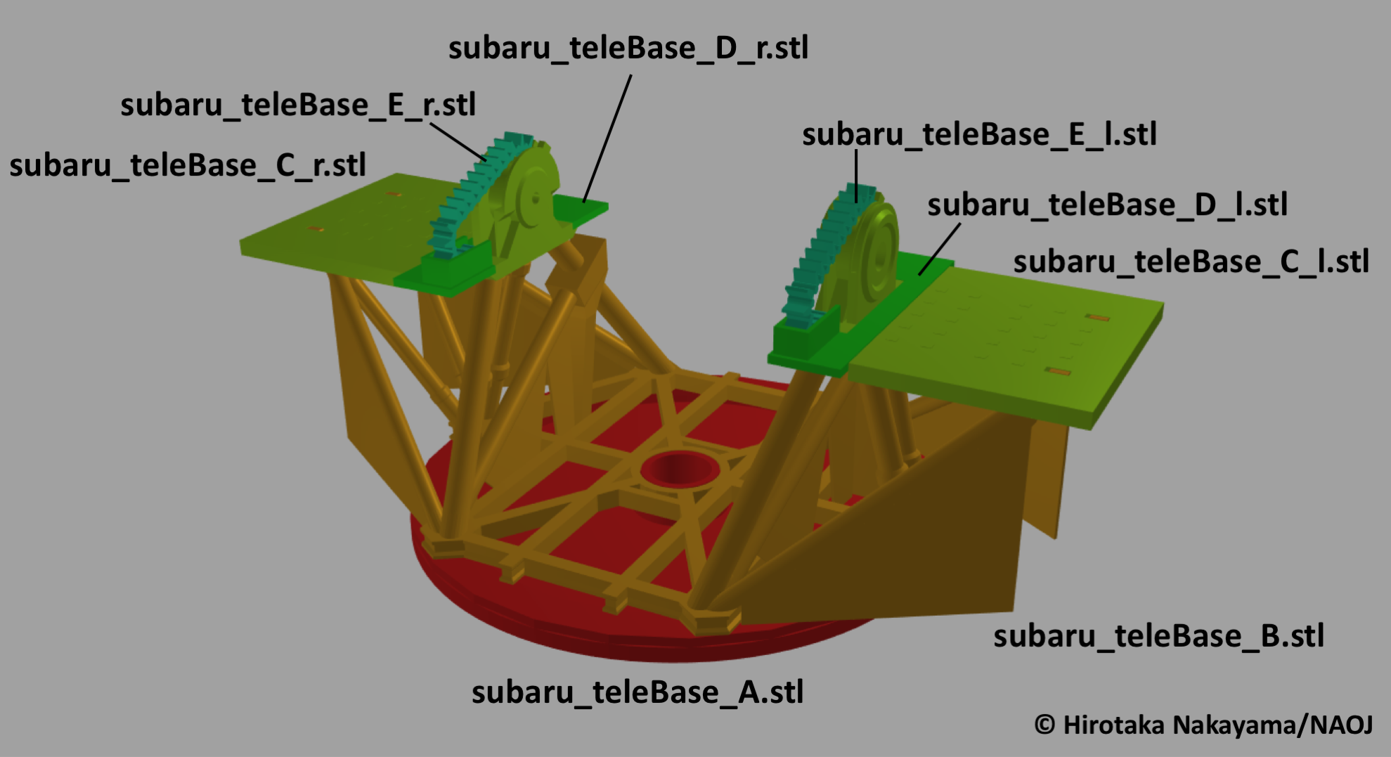
Fig. 2 The base section
As shown in Fig. 2, print the eight (8) parts with file names starting with "subaru_teleBase". Note that "C", "D", and "E" have a left ("l") and right ("r") version, both of which are needed to construct the telescope.
The Simplified Version
- Download package including stl files and manual (zip file, 2.1 MB)
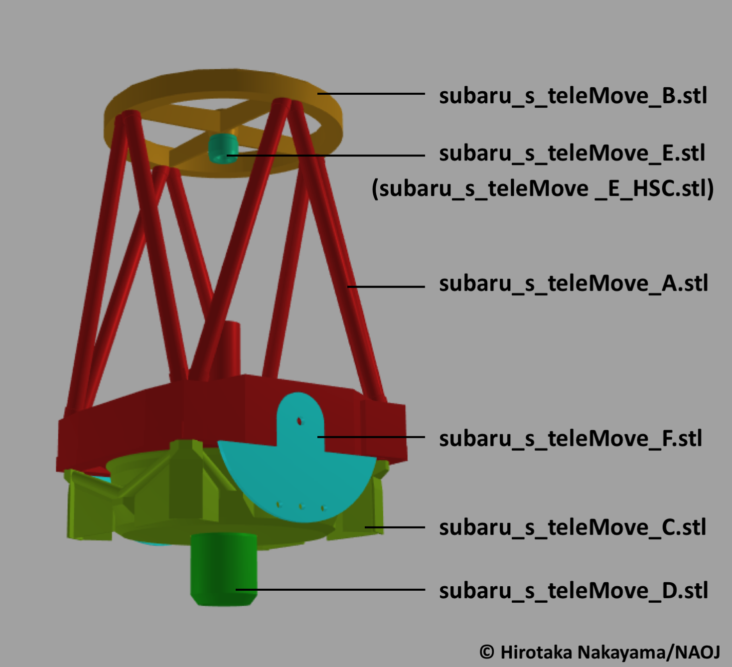
Fig. 3 The movable section
Print one (1) copy of the five (5) parts "teleMove_A" to "teleMove_E" and two (2) copies of "teleMove_F". The part "teleMove_E_HSC" is optional; it is interchangeable with "teleMove_E".
In Fig. 3, the secondary mirror ("teleMove_E") is mounted at the center of the top ring ("teleMove_B"). Same as the real telescope, the secondary mirror can be exchanged with Hyper Suprime Cam ("teleMove_E_HSC"), a giant digital camera with an extremely wide field of view.
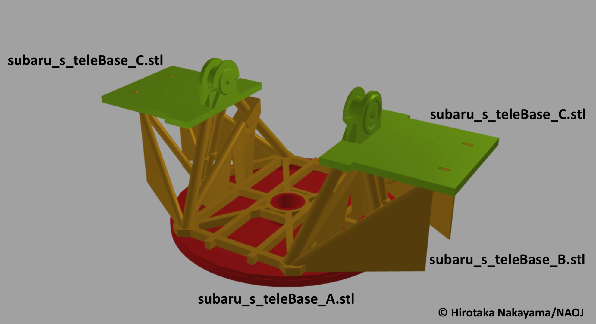
Fig. 4 The base section
As shown in Fig. 4, print one (1) copy each of the parts "subaru_s_teleBase_A" and "subaru_s_teleBase_B" and two (2) copies of "subaru_s_teleBase_C".
The Primary Mirror
Take a 20-cm (7.9-inch) diameter vinyl-chloride transparency half-sphere and use a compass cutter to cut out a 7.4-cm (2.9-inch) diameter (3.7-cm/1.5-inch radius) circle to use as the primary mirror. (Cut out a small hole at the center of the "mirror" with the minimum radius that your compass cutter can make.) If needed, download the template sheet and print it out on A4 (210 mm × 297 mm/8.3 inch × 11.7 inch) paper. (template sheet for Letter paper is also available.)
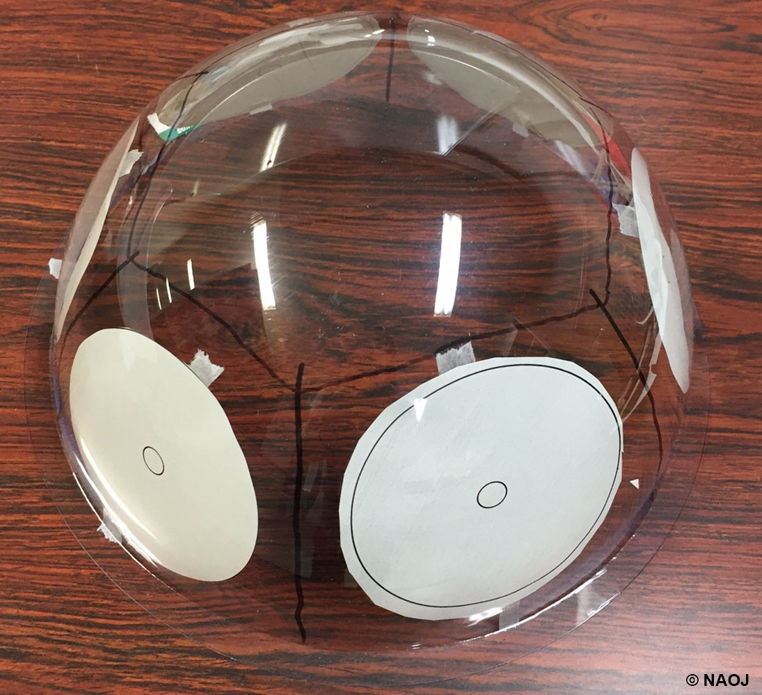
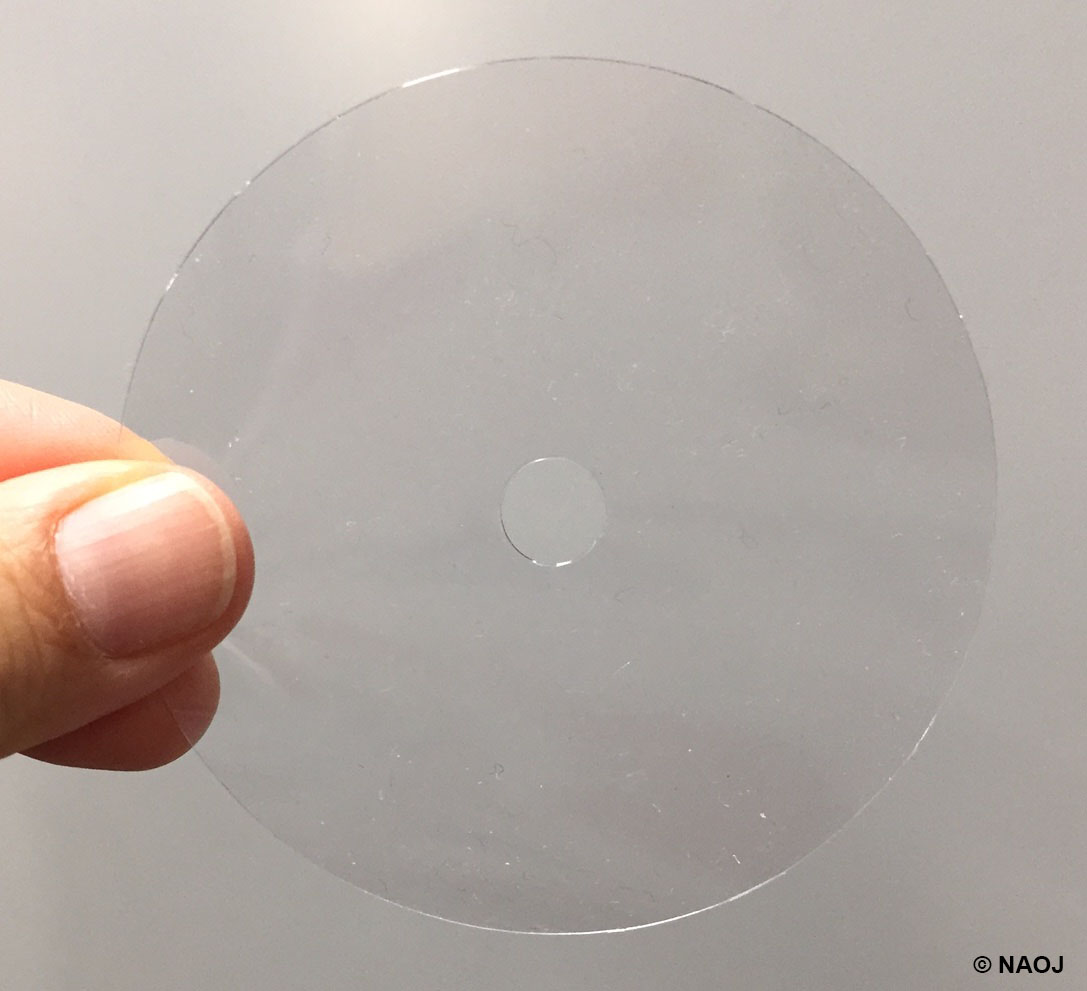
Fig. 5 The 20-cm (7.9-inch) diameter transparency half-sphere with primary mirror template sheets attached (left), and a "primary mirror" cut out with a compass cutter (right).
Paste the primary mirror onto the "teleMove_C" part with an ABS adhesive bond before assembling the movable section. The curvature of the "teleMove_C" part is designed to fit the 7.4-cm (2.9-inch) diameter primary mirror cut out from the 20-cm (7.9-inch) half-sphere.
Connecting the Movable and Base Sections
After assembling the movable section and the base section as shown in Figs. 1 and 2 (or Figs. 3 and 4 for the simplified version), connect these sections with two (2) M4 bolts and hexagonal nuts. For the models shown in the figures, stainless-steel, pan head M4 bolts (and nuts) are used. For best results, we suggest placing a 0.8-mm thick washer between the sections when you connect them.
M4 bolt: 4-mm width × 20-mm length, 0.7 mm pitch
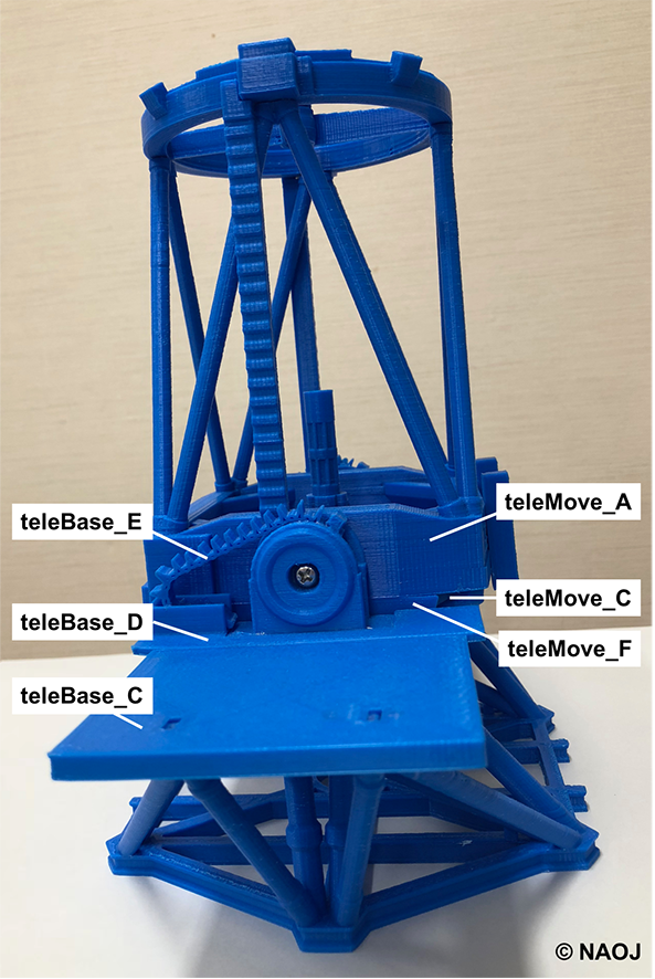
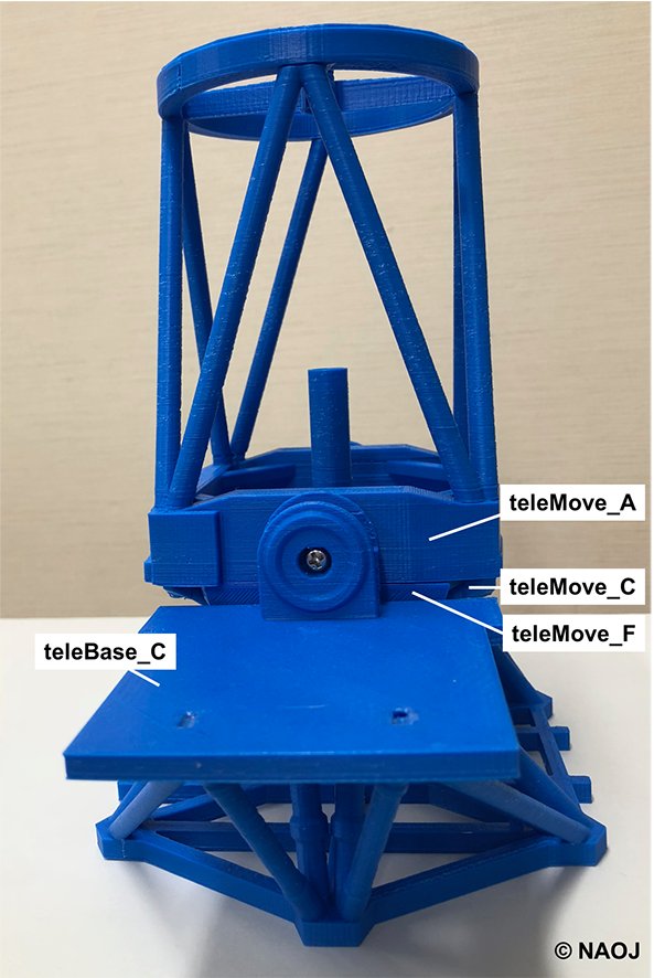
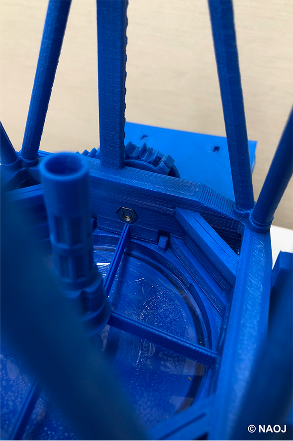
Fig. 6 Side views of the detailed (left) and the simplified (middle) versions. The head of the bolt is seen in each model. (right) Inside view showing the hexagonal nut.
First, insert a hexagonal nut into the hexagonal hole in the moveable section from the inside (Fig. 6 right). Line up the movable section and the base section (placing a washer between the sections is advised but optional). Then, insert an M4 bolt into the "teleBase_C" part from the outside until it makes contact with the nut and screw it into the nut (Fig. 6 left/middle).
Repeat this process for the other side. Do not over-tighten the bolts. The movable section should tilt freely around the axis formed by the bolts, but should hold its angle when positioned, rather than slipping down.
Credit of the Models
- The stl files were made by Hirotaka Nakayama (4D2U Project, NAOJ)
- The models were suprevised by the Subaru Telescope Model Project
 Go to the "Structure of the telescope (where to touch the models)" page
3D Tactile Models Home Page > The Subaru Telescope > How to Make the Models